Capsule Design
-
2015 08 30 08.40.56 2015 08 30 08.40.56
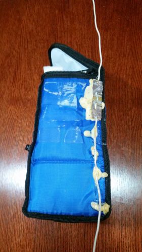
A 2 meter dipole antenna can be made with a scrap of blank PCB material. Carve a channel to separate the two halves of the PCB and drill a hole through one side, large enough to pass a piece of coax. Pass the coax through the hole and solder the braid to that side, and then carefully attach the center conductor to the other side. Take two pieces of 12-14ga wire cut to 19.25" long and solder one on each side. Mount the antenna to the side of a capsule. I cover the antenna in duct tape to give it plenty of mechanical stability.
-
2015 08 30 08.41.03 2015 08 30 08.41.03
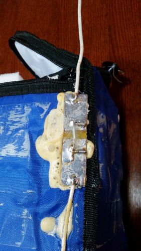
A close up of the center unit. The dimension of the PCB are not critical, only the length of the two wires. They should be 19.25" long each. Mount the dipole so that the elements are vertical during the flight. It does not matter whether the coax braid or the coax center conductor is on top.
-
2015 08 30 08.41.09 2015 08 30 08.41.09
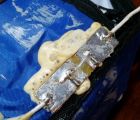
Another close up of the PCB. Note that the solder side of the PCB has been coated in epoxy for rigidity and to insulate it from anything it may come in contact with.
-
2015 08 30 08.41.53 2015 08 30 08.41.53
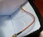
The coax is passed into the capsule through a small slit. I buy 12-18" pre-made coax cables with SMA connectors on both ends. I cut the cables in half to make two separate antennas out of a single patch cable.
-
2015 08 30 08.42.26 2015 08 30 08.42.26
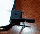
The Raspberry Pi camera mounts, 3D printed. The camera seen hanging will be mounted to the under side of the piece sticking out to the right, and will face up towards the balloon.
-
2015 08 30 08.42.41 2015 08 30 08.42.41
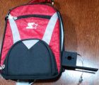
A 3D printed camera mount, bolted to the side of its capsule.
-
2015 08 30 19.06.49 2015 08 30 19.06.49
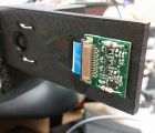
I used surplus 1/4 watt resistors placed through the mounting holes to mount the camera PCB's. It was lighter and cheaper than buying the odd-ball small hardware (the holes are smaller than a 440 bolt).
-
2015 08 30 19.07.03 2015 08 30 19.07.03
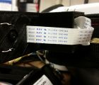
All of the ribbon cables are passing over the top, and enter the capsule through a small slit. To the left you can see the leads of the 1/4 watt resistor twisted together to hold the camera boards in place.
-
2015 08 31 21.41.36 2015 08 31 21.41.36
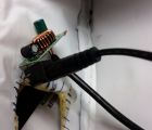
To supply 5V DC to the Rasberry Pi, I bought a cheap USB car charger from the discount store and took its case off. I soldered a 2.1mm barrel connector across the input terminals, and soldered a short micro USB cable to the 5V output terminals. The car charger is capable of running down into the ~6 volt range, which is perfect for a 2 cell LiPo battery.
-
2015 11 03 21.04.21 2015 11 03 21.04.21
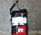
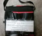
A capsule made out of a lunch bag. The dipole can be seen in the background, and is covered by the black duct/Gorilla tape. I reinforced the carry handle with a second piece of nylon webbing which extends down below the capsule. I have large (heavy duty) split ring key rings on the top and bottom to attach the load line to other capsule above and below.
-
2015 11 03 21.04.30 2015 11 03 21.04.30
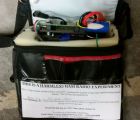
A close up of the capsule. I leave the duct tape on between flights, and just peal off the clear packing tape to swap out the harmless package notice before each flight.
-
2015 11 03 21.04.45 2015 11 03 21.04.45
Accessing the inside of the capsule is a simple matter of unzipping the bag. I fill inside of the capsule with a piece of foam, such as the stuff that you put inside of seat cushions. The foam is easily carved with a sharp filleting knife. The GPS antenna is on the left, with a clear view of the sky above through a thin layer of soft plastic.
-
2015 11 03 21.04.57 2015 11 03 21.04.57
The avionics (in this case an ArduinoTrack) are mounted to a 3D printed carrier board. On the bottom of the board is the 2m radio transmitter which is attached to the SMA connector going to the dipole.
-
2015 11 03 21.05.06 2015 11 03 21.05.06
The ArduinoTrack is mounted to the carrier board, next to the 7.4V lipo battery. The 2m transmitter is mounted to the bottom side of the board, as far away from the GPS antenna as possible. Starting the transmitter on the morning of the flight is a simple matter of plugging in the 2.1mm barrel connector.
-
2015 11 03 21.05.22 2015 11 03 21.05.22
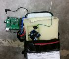
Inside of the foam I have carved out areas to hold other avionics, cameras, etc. Here is a 434MHz transmitter module from SparkFun that is modulated with a little Arduino controller. It services as a small backup RF beacon.
-
2015 11 03 21.05.52 2015 11 03 21.05.52
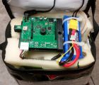
Another view of the ArduinoTrack controller sitting on the top of the capsule, ready to be plugged in.
-
2015 11 03 21.08.29 2015 11 03 21.08.29
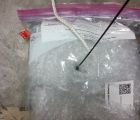
For a very light weight capsule, some regular bubble wrap will keep the transmitter quite warm. Despite the sealed bubbles, they survive just fine up at altitude and back down. I put the bubble-wrap-encased controller board inside of a ziplock baggy to keep everything together. Sticking out the top is a whip antenna, and out the bottom is a 19.25" antenna counter-poise. To the upper-left is a small external temperature sensor.
-
2015 11 03 21.09.13 2015 11 03 21.09.13
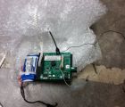
Pulling the controller out of the bag is a small 2-cell lipo battery on a 3D printed carrier board. The load line passes through the hole in the middle of the carrier board and a knot in the bottom of the rope keeps the controller suspended mid-string. The 19.25" antenna counter poise is REQUIRED for use with a whip antenna, otherwise you will lose data connectivity with the capsule after about 30,000'.
-
2015 11 03 21.09.26 2015 11 03 21.09.26
Here you can see the ArduinoTrack mounted to the carrier board. The whip antenna extends up, and the counterpoise is attached to the RF ground on the bottom of the PCB. The counterpoise just hangs loosely below the capsule.
-
2015 11 03 21.09.54 2015 11 03 21.09.54
All capsules use heavy duty split-rings to interconnect the load lines. This makes for quick disassembly in the field during retrieval, and saves a lot of re-rigging between flights.
A 2 meter dipole antenna can be made with a scrap of blank PCB material. Carve a channel to separate the two halves of the PCB and drill a hole through one side, large enough to pass a piece of coax. Pass the coax through the hole and solder the braid to that side, and then carefully attach the center conductor to the other side. Take two pieces of 12-14ga wire cut to 19.25" long and solder one on each side. Mount the antenna to the side of a capsule. I cover the antenna in duct tape to give it plenty of mechanical stability.
A close up of the center unit. The dimension of the PCB are not critical, only the length of the two wires. They should be 19.25" long each. Mount the dipole so that the elements are vertical during the flight. It does not matter whether the coax braid or the coax center conductor is on top.
Another close up of the PCB. Note that the solder side of the PCB has been coated in epoxy for rigidity and to insulate it from anything it may come in contact with.
The coax is passed into the capsule through a small slit. I buy 12-18" pre-made coax cables with SMA connectors on both ends. I cut the cables in half to make two separate antennas out of a single patch cable.
The Raspberry Pi camera mounts, 3D printed. The camera seen hanging will be mounted to the under side of the piece sticking out to the right, and will face up towards the balloon.
A 3D printed camera mount, bolted to the side of its capsule.
I used surplus 1/4 watt resistors placed through the mounting holes to mount the camera PCB's. It was lighter and cheaper than buying the odd-ball small hardware (the holes are smaller than a 440 bolt).
All of the ribbon cables are passing over the top, and enter the capsule through a small slit. To the left you can see the leads of the 1/4 watt resistor twisted together to hold the camera boards in place.
To supply 5V DC to the Rasberry Pi, I bought a cheap USB car charger from the discount store and took its case off. I soldered a 2.1mm barrel connector across the input terminals, and soldered a short micro USB cable to the 5V output terminals. The car charger is capable of running down into the ~6 volt range, which is perfect for a 2 cell LiPo battery.
A capsule made out of a lunch bag. The dipole can be seen in the background, and is covered by the black duct/Gorilla tape. I reinforced the carry handle with a second piece of nylon webbing which extends down below the capsule. I have large (heavy duty) split ring key rings on the top and bottom to attach the load line to other capsule above and below.
A close up of the capsule. I leave the duct tape on between flights, and just peal off the clear packing tape to swap out the harmless package notice before each flight.
Accessing the inside of the capsule is a simple matter of unzipping the bag. I fill inside of the capsule with a piece of foam, such as the stuff that you put inside of seat cushions. The foam is easily carved with a sharp filleting knife. The GPS antenna is on the left, with a clear view of the sky above through a thin layer of soft plastic.
The avionics (in this case an ArduinoTrack) are mounted to a 3D printed carrier board. On the bottom of the board is the 2m radio transmitter which is attached to the SMA connector going to the dipole.
The ArduinoTrack is mounted to the carrier board, next to the 7.4V lipo battery. The 2m transmitter is mounted to the bottom side of the board, as far away from the GPS antenna as possible. Starting the transmitter on the morning of the flight is a simple matter of plugging in the 2.1mm barrel connector.
Inside of the foam I have carved out areas to hold other avionics, cameras, etc. Here is a 434MHz transmitter module from SparkFun that is modulated with a little Arduino controller. It services as a small backup RF beacon.
Another view of the ArduinoTrack controller sitting on the top of the capsule, ready to be plugged in.
For a very light weight capsule, some regular bubble wrap will keep the transmitter quite warm. Despite the sealed bubbles, they survive just fine up at altitude and back down. I put the bubble-wrap-encased controller board inside of a ziplock baggy to keep everything together. Sticking out the top is a whip antenna, and out the bottom is a 19.25" antenna counter-poise. To the upper-left is a small external temperature sensor.
Pulling the controller out of the bag is a small 2-cell lipo battery on a 3D printed carrier board. The load line passes through the hole in the middle of the carrier board and a knot in the bottom of the rope keeps the controller suspended mid-string. The 19.25" antenna counter poise is REQUIRED for use with a whip antenna, otherwise you will lose data connectivity with the capsule after about 30,000'.
Here you can see the ArduinoTrack mounted to the carrier board. The whip antenna extends up, and the counterpoise is attached to the RF ground on the bottom of the PCB. The counterpoise just hangs loosely below the capsule.
All capsules use heavy duty split-rings to interconnect the load lines. This makes for quick disassembly in the field during retrieval, and saves a lot of re-rigging between flights.
-
A 2 meter dipole antenna can be made with a scrap of blank PCB material. Carve a channel to separate the two halves of the PCB and drill a hole through one side, large enough to pass a piece of coax. Pass the coax through the hole and solder the braid to that side, and then carefully attach the center conductor to the other side. Take two pieces of 12-14ga wire cut to 19.25" long and solder one on each side. Mount the antenna to the side of a capsule. I cover the antenna in duct tape to give it plenty of mechanical stability.
-
A close up of the center unit. The dimension of the PCB are not critical, only the length of the two wires. They should be 19.25" long each. Mount the dipole so that the elements are vertical during the flight. It does not matter whether the coax braid or the coax center conductor is on top.
-
Another close up of the PCB. Note that the solder side of the PCB has been coated in epoxy for rigidity and to insulate it from anything it may come in contact with.
-
The coax is passed into the capsule through a small slit. I buy 12-18" pre-made coax cables with SMA connectors on both ends. I cut the cables in half to make two separate antennas out of a single patch cable.
-
The Raspberry Pi camera mounts, 3D printed. The camera seen hanging will be mounted to the under side of the piece sticking out to the right, and will face up towards the balloon.
-
A 3D printed camera mount, bolted to the side of its capsule.
-
I used surplus 1/4 watt resistors placed through the mounting holes to mount the camera PCB's. It was lighter and cheaper than buying the odd-ball small hardware (the holes are smaller than a 440 bolt).
-
All of the ribbon cables are passing over the top, and enter the capsule through a small slit. To the left you can see the leads of the 1/4 watt resistor twisted together to hold the camera boards in place.
-
To supply 5V DC to the Rasberry Pi, I bought a cheap USB car charger from the discount store and took its case off. I soldered a 2.1mm barrel connector across the input terminals, and soldered a short micro USB cable to the 5V output terminals. The car charger is capable of running down into the ~6 volt range, which is perfect for a 2 cell LiPo battery.
-
A capsule made out of a lunch bag. The dipole can be seen in the background, and is covered by the black duct/Gorilla tape. I reinforced the carry handle with a second piece of nylon webbing which extends down below the capsule. I have large (heavy duty) split ring key rings on the top and bottom to attach the load line to other capsule above and below.
-
A close up of the capsule. I leave the duct tape on between flights, and just peal off the clear packing tape to swap out the harmless package notice before each flight.
-
Accessing the inside of the capsule is a simple matter of unzipping the bag. I fill inside of the capsule with a piece of foam, such as the stuff that you put inside of seat cushions. The foam is easily carved with a sharp filleting knife. The GPS antenna is on the left, with a clear view of the sky above through a thin layer of soft plastic.
-
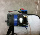
The avionics (in this case an ArduinoTrack) are mounted to a 3D printed carrier board. On the bottom of the board is the 2m radio transmitter which is attached to the SMA connector going to the dipole.
-
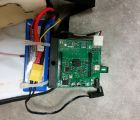
The ArduinoTrack is mounted to the carrier board, next to the 7.4V lipo battery. The 2m transmitter is mounted to the bottom side of the board, as far away from the GPS antenna as possible. Starting the transmitter on the morning of the flight is a simple matter of plugging in the 2.1mm barrel connector.
-
Inside of the foam I have carved out areas to hold other avionics, cameras, etc. Here is a 434MHz transmitter module from SparkFun that is modulated with a little Arduino controller. It services as a small backup RF beacon.
-
Another view of the ArduinoTrack controller sitting on the top of the capsule, ready to be plugged in.
-
For a very light weight capsule, some regular bubble wrap will keep the transmitter quite warm. Despite the sealed bubbles, they survive just fine up at altitude and back down. I put the bubble-wrap-encased controller board inside of a ziplock baggy to keep everything together. Sticking out the top is a whip antenna, and out the bottom is a 19.25" antenna counter-poise. To the upper-left is a small external temperature sensor.
-
Pulling the controller out of the bag is a small 2-cell lipo battery on a 3D printed carrier board. The load line passes through the hole in the middle of the carrier board and a knot in the bottom of the rope keeps the controller suspended mid-string. The 19.25" antenna counter poise is REQUIRED for use with a whip antenna, otherwise you will lose data connectivity with the capsule after about 30,000'.
-
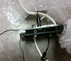
Here you can see the ArduinoTrack mounted to the carrier board. The whip antenna extends up, and the counterpoise is attached to the RF ground on the bottom of the PCB. The counterpoise just hangs loosely below the capsule.
-
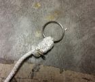
All capsules use heavy duty split-rings to interconnect the load lines. This makes for quick disassembly in the field during retrieval, and saves a lot of re-rigging between flights.


